Hi there, i purchased the ESP32 38pin board that i have some trouble identifying (USB-C). Plus i don’t really know how to wire to a SRX882 (and a STX882) module. I connected the G27 to the DATA of the RX and the G12 to the DATA of the TX, GND to - and VCC to +
I try to intercept a signal from a dumb/generic doorbell transmitter and i’m not getting anything from it (the transmitter from the doorbell is a CMT2150A, here’s a breakdown of the doorbell). I have no other way of testing if my setup works and on top of that i’m not sure if any library could get something…? Any help would be appreciated.
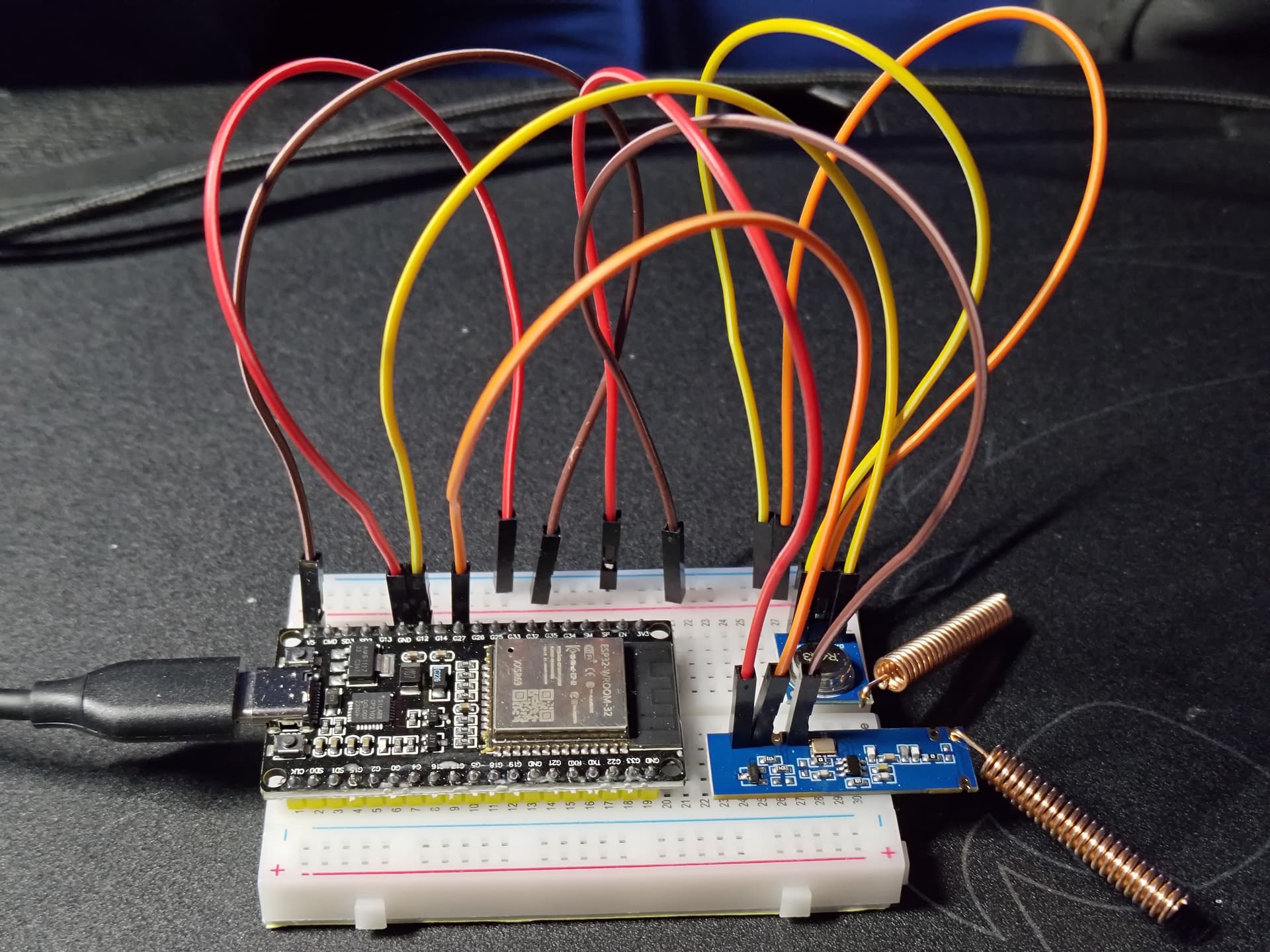
Could you post a photo of your ESP32 38pin board?
It sounds as if you followed the pin out connections on the setup page, so things should be working fine.
And which binary/binaries did you then install on your ESP32 with the SRX882 and a STX882 attached?
And do you possibly have any other RF devices or remotes which might be useful for testing if the connections are all correct?
Maybe also try the + to 3V3, as displayed in the pinout diagram, even though they should have a wide voltage range from 2.4V to 5.5V.
Hey, thanks for your reply, here’s a photo attached, you can have a look at this too. I tried esp32dev-multi_receiver-pilight, tried some others too but to no avail… EDIT: tried 3V3 and 5V… I also have some other devices, don’t know however if they’re 433mhz but they’re not recognized either… Had a Lilygo Lora32 before that could detect some signals from the neighborhood but couldn’t test RF or Pilight libraries, that’s why this could be a solution, see this thread…
The G27 looks to be entering to the wrong pin of the RX module to me, from what I can make out. Can you verify all the connections again yourself with the link I posted above?
Unless your module, which looks slightly different to the one I have and which is depicted on the diagram, has different pin assignments.
Also putting DuPont cables directly into the receiving holes of the modules is not really a good idea, as no proper contact is assured like that. The best thing would be to solder pins on the RX and TX module, then put them into the breadboard and put the DuPont cable ends into the related rows, similar to how you did it with the ESP32.
Best to leave out a pin for the empty not used RX module connection, so as not to mistakenly connect to it in the future.
Currently I think you do not have proper connections on the RX/TX modules at all, even if you switch the one I mentioned above to the correct one.
Only with proper connections will it be worth testing out the different RF protocols.
Hey, thanks for the reply, yes, i temporarily switched the DATA and CS pin because i read somewhere that could be the issue and i photographed it like that before switching back. I think you’re right by saying that i won’t come along soldering pins to the module, it came without so i guess i need to get some of those and try again ![]()
I’m afraid so, as currently I don’t think that you have any contact with the DuPont cables’ thin pins with any of the contact rings on the top and bottom of the pin holes.
You could possibly try to manually hold the three cable pins to the top circular contacts around the pin holes of the RX unit while someone else switches the sender, and you both monitor any reception with MQTT Explorer, while switching through the different protocols on the gateway - but soldering proper pins to the receiver and transmitter will definitely be the more reliable way.