I know that this is an older thread but this was never really answered and there may be others finding this and having the same question.
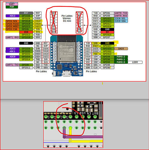
On a Wemos D1 MINI (esp8266), you’ll see pins 5V, GND, 4 & D3 (and four more.) The D4 and D3 are GPIO2 and GPIO0, respectively. But on a Wemos 32 D1 mini, you see the innermost pins on the right that have white around them (on the board itself) are 5V GND, D4 & D3 but they are also labeled as VCC, GND, IO16 & IO17. So the pins in white are the same layout (5V, GND, four general IO, RXD and TXD) on both boards so they can use the same hats. But because the actual GPIO numbers are not the same, you need the code adjusted for the pins/CPU. So if the code has “#define CLK 2” (GPIO2 or D4) for the esp8266, it’d need to be “#define CLK 15” for the corresponding pin on the esp32, etc if you want a 1-to-1 mapping of the physical locations on the Wemos esp8266 D1 and the white pins on the Wemos esp32 D1.
But when you’re seeing code for an esp32, D4 is never mapped to GPIO2 like it is on the esp8266. D4=GPIO4, D6 is GPPIO6, D1 is GPIO1, etc.
So ignore the two groups of pins outlined in red in the pinout diagram directly above the board as far as GPIO numbers go and directly convert “D27, D12, D18, 3V3, D23, D19, D5, GND” to “GPIO27, GPIO12, GPIO18, 3V3, GPIO23, GPIO19, DPIO5, GRD” (D5 being the one oddball because it’s the one showing as “SPI0:CS0 GPIO5 IO5” on the inner-left and corresponds to the ignored D8 on a esp8266 D1.) So the pins you’d need are highlighted in yellow in the upper part of the image.
You can confirm this in the documentation you links to (and shown in the second part of the image here) where they show a different esp32 board and using (GPIO) 27 and 12.
