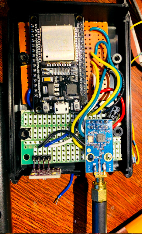
I’m working thru getting FSK demodulation working with a CC1101 in asynchronous mode for the rtl_433 port to the esp32 ( NorthernMan54/rtl_433_ESP#5 ) and was looking at leveraging the CC1101 carrier sense feature to determine start and end of signal for processing. As the signal and pulse timing for FSK signals is a lot shorter than ASK signals I need to use interrupt driven detection of signal start and end to be able to consistently detect signal start. My current approach was to watch RSSI signal strength during the Arduino LOOP, but the timing of this is challenging depending on what the ESP32 is doing and I found that it could potentially miss a significant portion of the FSK signal. My new design is to use a interrupt handler on the gpio connected to gdo0 and trigger based on CC1101 Carrier Sense, similar to how gdo2/gpio 4 is used to trigger on signal pulse.
So I went and enabled gd0 to be in carrier sense mode
SpiWriteReg(CC1101_IOCFG0,      0x0E);   // Carrier sense
SpiWriteReg(CC1101_AGCCTRL1, 0x10);   // Carrier sense relative +6db
And found that after flashing this configuration to my device I could no longer flash it again. After much digging into why I couldn’t flash the device I found this
Based on my read of that, I believe what is happening is that the cc1101 is holding gpio2/gdo0 high, and not allowing it to enter the serial bootloader. I then went and disconnected gpio2 and was able to successfully flash my esp32 again.
Also on a esp32 dev board, ( atleast on the ones I’m using ), gpio2 is also the LED
Looking at my layout, I’m thinking we should be recommending something like gpio25 instead. Looking at the available pins on the right side of a devboard, gpio15 is in pwm mode at boot and gpio21 and gpio22 are used by the i2c connection so am thinking will need to use a gpio from the left side.
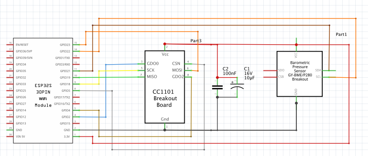
This would also qualify as a breaking change for users of the rtl_433 decoder package that have gdo0 connected to gpio2. I have raised this concern with the owner of the cc1101 driver package here Recommendation - On ESP32 don't connect gpio2 to gdo0 · Issue #78 · LSatan/SmartRC-CC1101-Driver-Lib · GitHub