Hello,
I’m completely new to OMG, MQTT, openHAB, and looking for some help.
My goal is to control my Warema sunblind via Openhab.
I have openHAB 2.5.10 with Mosquitto MQTT 1.5.7 running on RPI 4.
LinuxMint 20 with Arduino IDE 1.8.14 Build 2020/12/15
OMG V0.9.5 Modules: RF; RF2
Board: NodeMCU V1.0 ESP-12E ESP8266
RF: SRX882/STX882
OMG is running and i can see Messages in mosquitto
Serial output:
15:02:38.379 -> N: WiFi ok with manual config credentials
15:02:39.874 -> N: RF_EMITTER_GPIO: 3
15:02:39.874 -> N: RF_RECEIVER_GPIO: 4
15:02:39.874 -> N: Setup OpenMQTTGateway end
15:02:39.874 -> W: MQTT connection…
15:02:39.907 -> N: Connected to broker
15:02:39.907 -> N: Subject: /SYStoMQTT
15:02:39.907 -> N: Received json : {“uptime”:1,“version”:“version_tag”,“freemem”:45608,“rssi”:-70,“SSID”:“XXXXXXXX”,“ip”:“xxx.xxx.xxx.xxx”,“mac”:“xx:xx:xx:xx:xx:xx”,“wifiprt”:0,“modules”:“RFRF2”}
15:10:10.417 -> N: Subject: /433toMQTT
15:10:10.417 -> N: Received json : {“value”:15,“protocol”:4,“length”:7,“delay”:688}
15:10:10.417 -> N: no pub. dupl
15:10:10.417 -> N: Received json : {“value”:15,“protocol”:4,“length”:7,“delay”:688}
The RF;RF2 modules don’t seem to recognize the Warema EWFS signals of the transmitter.
On https://github.com/rfkd/aircontrol I found a module for the PI to control Warema EWFS devices.
Is there a module or a possibility to enable aircontrol or Warema EWFS devices for OMG ?
I appreciate all your help
Henk
Hello,
Did you try to send with OMG the message that you are receiving when using the remote control?
Hi,
No I didn’t try to send anything yet. The messages received in the log are from an other transmitter, just to verify the receiver setup is working.
When I push the buttons on the Warema remote control I don’t see anything happening on the serial output.
I want to try the ReceiveDemo examples to see if something is coming through.
In the script it says “Receiver on interrupt 0 => that is pin #2”, which GPIO is that on the ESP8266 ?
Thanks,
Henk
Hi,
ReceiveDemo will not add value to OMG with RF gateway, if you setup receive data you don’t need to test with ReceiveDemo.
I would test with Pilight gateway instead and see if you have something coming.
Could you point mewhere you found this?
gpio 0 is D3 on ESP8266
Hi,
The “Receiver on…” comment is in rc-switch/examples ReceiverDemo_simple.ino and _advanced.ino.
I tried PiLight, but that didn’t give output either.
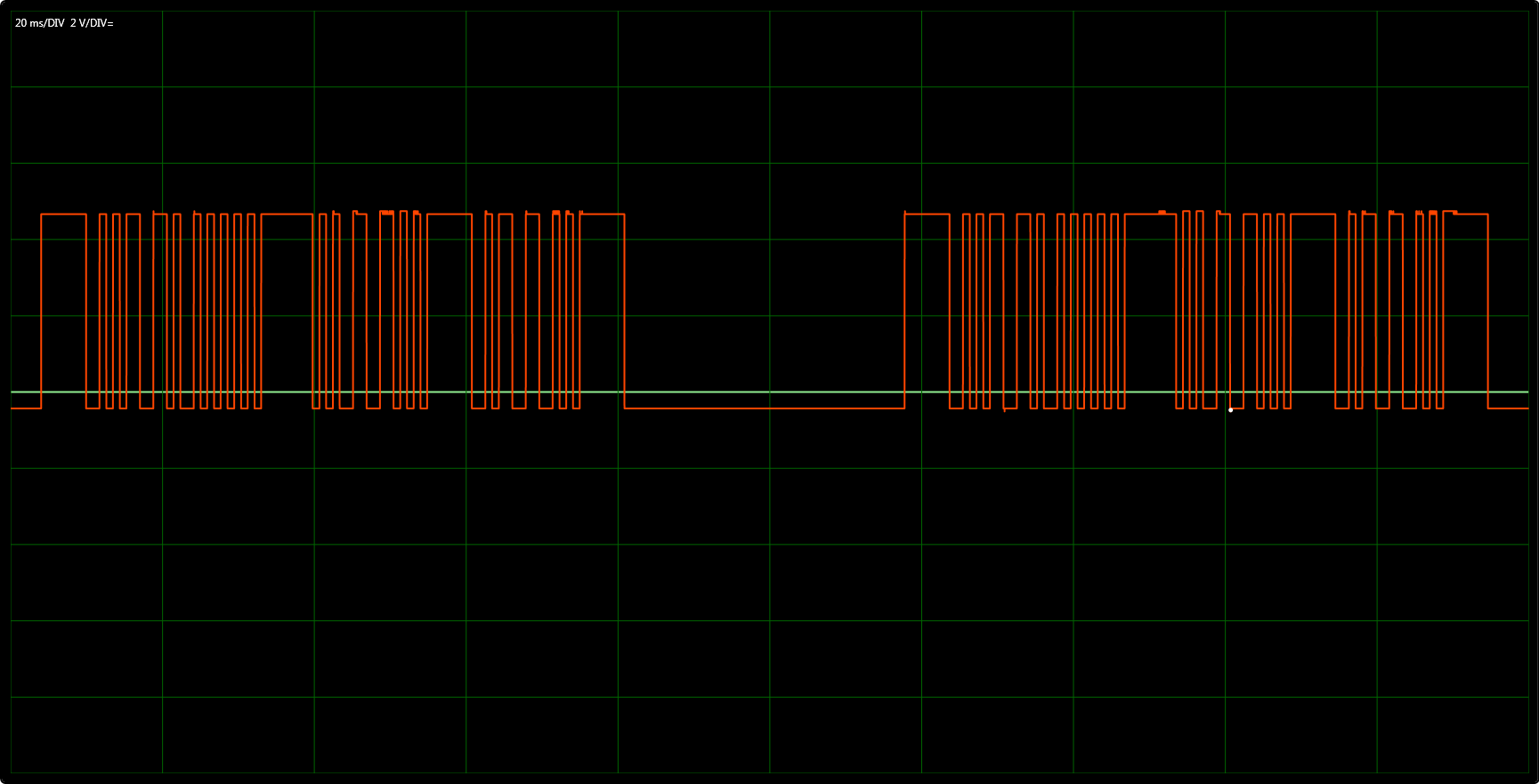
I will do some further research. I attached the complete “Close” button signal from the remote control. Maybe this helps for selecting the right module.
It doesn’t seem to be a “difficult” signal to decode, did you take a look to the decoding tutorial of rcswitch:
I spent many hours trying to figure-out how to control my sun blinds. I doubted at times whether they even operated on 433MHz, as I couldn’t get anything out of the regular ‘sniffer’ sketches.
I eventually captured and analysed the waveform using Audacity, and re-created the codes using a sketch that simply modulates the output of an ESP8266 in the correct way to simulate the waveform (I don’t use OMG for this).
More info here:
It’s worth reading through the entire topic, as it has some useful insights into capturing and recreating 433 waveforms.
Pete.
@PeteKnight
Thanks for the info, I will have a look at it, especialy at the part of recreating the waveforms.
Since yesterday I booked some progress.
I got the nodemcuv2-pilight/ESPiLight/examples Recieve and Receive_raw working.
With receive_raw.ino I could capture the signals from my remote and after pasting the captured signal data in the rc-switch raw data viewer it matches the pulses of my scoope output. It even converts the signal into the right pulse sequence  Only the long low of the sync is not captured. The capture starts at the first low to high edge of the sync.
12:47:52.433 -> RAW signal: 1762 909 864 909 871 1783 1763 1785 882 892 1765 902 874 902 873 902 874 902 874 900 875 6786
12:47:52.443 -> string format: c:0111100011011111111112;p:1762,909,6786@
12:47:52.443 -> RAW signal: 895 880 891 883 1773 1777 1768 1781 886 888 884 889 890 5887
12:47:52.488 -> string format: c:00001111000002;p:895,1773,5887@
12:47:52.488 -> RAW signal: 1780 890 884 1774 1773 1777 1771 897 878 898 877 5898
12:47:52.488 -> string format: c:011000011112;p:1780,890,5898@
Now I have to figure out how to process and (re)send the data.
Henk
Hi,
Try maybe the raw sending of Pilight :
Hi,
i modified Transmit_Raw.ino a bit and included a Loop with a delay, a Loop count to see on the Serial output if the program is running and a signal repeat count.
With the modified program I could reconstruct the transmit signal.
Now how do I get the ESPiLight Receive_Raw and Transmit raw integrated in OMG ?
/*
Basic ESPiLight transmit RAW signal example
https://github.com/puuu/espilight
*/
#include <ESPiLight.h>
#define TRANSMITTER_PIN 13 // GPIO13 - D7
ESPiLight rf(TRANSMITTER_PIN);
int length = 0;
uint16_t codes[MAXPULSESTREAMLENGTH];
int LoopCnt = 0;
int Repeat = 2;
void setup() {
Serial.begin(115200);
// get pulse train from string (format see: pilight USB Nano)
length = rf.stringToPulseTrain(
“c:20111100011011111111113111100001111120110000111124;p:”
“1780,890,5888,6800,34800@”,
codes, MAXPULSESTREAMLENGTH);
}
// Repeat every 200 ms
void loop() {
// transmit the pulse train
rf.sendPulseTrain(codes, length, Repeat);
LoopCnt++;
Serial.print("Loop count: “);
Serial.print(LoopCnt);
Serial.print(” Length: ");
Serial.println(length);
delay(200);
}
The pilight raw transmitter is already integrated. You have the info into the docs. Not the receiver.
Did you ever get it to work with OMG? I also have a warema EWFS and would love to have a simple solution. Thanks!
The ESP was very instable, probably some memory leak.
With testing I didn’t notice, but wenn The ESP was running longer the time between system crashes got shorter and shorter.
I never got to a practical working solution