Further to the previous post, I opened a new post.
I have this GS-WDS07 433Mhz Door sensor and i want to connect instead the REED Switch a water leak sensor (2 pins only with cable).
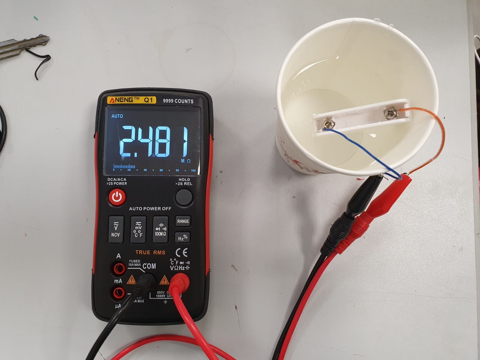
So I dismantled the REED and measured its resistance and it came out at about 50 ohms, I tried to put a similar resistor but it immediately turned on the sensor, I also connected only the wires instead of the REED and tested with a glass of water but it did not activate the sensor. I only measured the resistance of the sensor and it gave 1.5M ohms and put it in a glass of water (obviously disassembled and not connected to the RF module) it gave me the same 1.5M ohms value sometimes cut to 2.5M ohms.
I ordered a lot of such door sensors and I stayed 5 and thought of turning them into water sensors, I didn’t think it was that complicated.
Why are you going to add a transistor? What exactly would he do?
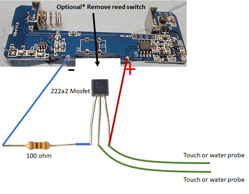
The transistor will act as an amplifier of the current detected when water goes through your sensor, it will let pass more current compared to the water sensor itself.
In my point of view for a security related device like a water detector I would go for off the shelves, just my thoughts.
There is something I do not understand, REED SWITCH is just a standard two pins switch, the water sensor I have is two-pin with two wires that once the water touches both legs is short-formed.
My question is why can it be used this way? Doesn’t water shorten?
Sorry but I don’t get it, could you be more accurate please:
-Water sensor impedance without water
-water sensor impedance with water
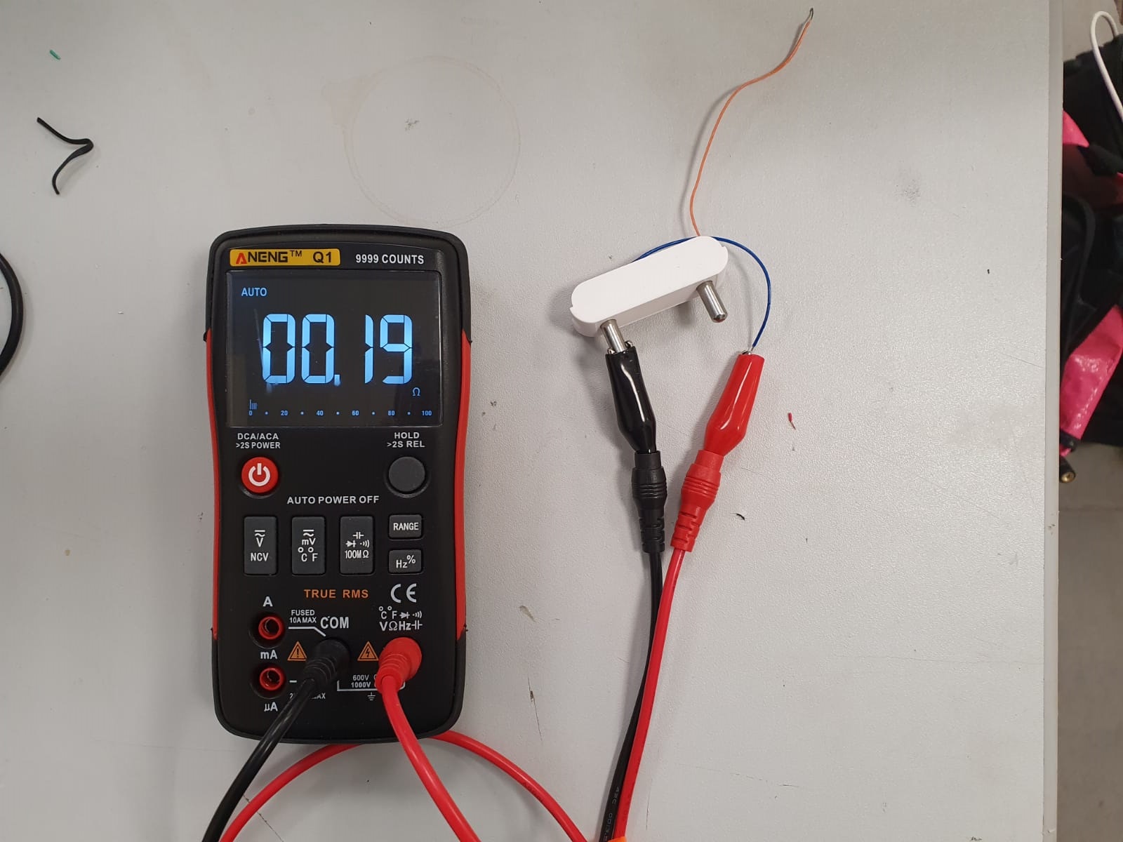
-reed switch impedance when close
-reed switch impedance when far
Yes, to make it works you should build a circuit that generate an open switch when you have water and a close switch when you don’t have water.
You should better ask on a forum dedicated to electronics, you will have better chances to find support.
After many trials I have answer for other DIYer who wants to do something, I finally got it. It was very simple, I will post proper answer with semantics soon.